Description
Product details
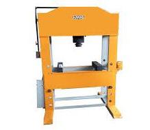
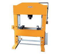
1 DESCRIPTION OF MACHINE 1.1 HYDRAULIC PRESS 2 QUANTITY REQUIRED - 1 No. 3 SCOPE OF SUPPLY 3.1 The basic machine 3.2 Standard ( Essential) accessories/equipments 3.3 Recommended Maintenance Spares as ordered. 3.4 Packing and Forwarding (including Transportation) to HVF. 3.5 Construction of complete Foundation (if applicable), 3.6 Final Proving trials at HVF. 4 PURPOSE FOR WHICH THE MACHINE IS INTENDED 4.1 The machine is intended for carrying out for bend removal & straightening operations of Torsion Bar made from high alloy spring steel. The machine should have the capability to do bend removal & straightening operations for Torsion Bar to Drg.No. 172.51.016 component to entire length. The machine shall be designed and supplied in tooled up condition. 5 TECHNICAL SPECIFICATION 5.1 Capacity : 40Ton or more 5.2 Type of Machine: Open Throat C-Frame type Hydraulic Press 5.3 Type of Operation: Foot pedal and Hand lever type 5.4 Ram forward capacity (minimum) : 400 kN 5.5 Ram return capacity (minimum) : 155 kN 5.6 Ram Stroke(minimum) : 400 mm 5.7 Daylight (minimum) : 630 mm 5.8 Throat (minimum) : 220 mm 5.9 Table size (minimum) : 450 x 560 mm 5.10 T Slot : T22(IS:2013H12) 5.11 Working Height (minimum) : 750 mm 5.12 Ram Approach speed (minimum ) : 50 mm/second 5.13 Ram Pressing speed : 10 - 20 mm/second 5.14 Ram Return speed (minimum) : 100 mm/second 5.15 Ram speed should be control by manualy as well as automatic. 6 STANDARD (ESSENTIAL) ACCESSORIES / EQUIPMENTS: 6.1 Tool kit of reputed make containing 1 set of allen keys ranging from 2.5mm to 20mm, 1 set of spanners ranging from 6mm to 31mm, In & Out circlip extractors, medium size adjustable spanner, screw driver, cutting player and each one number of other tools if any required for daily working & maintenance of the machine. 6.2 Hydraulic system with initial fill of oil 6.3 Bar straightening attachment in accordance with clauses from 6.3.1 to 6.3.6 for bend removal / straightening of bars of diameters 20mm to 55mm and lengths varying from 1 meter to 2.4 meters. A nominal sketch of the existing press model is enclosed for ready reference. 6.3.1 1 No. straightening table of suitable length in accordance with clause No. 6.3 6.3.2 1 No. throughout sliding bed containing 2 No.s of dead centers with locking facility (with springs for suspension duiring straightening) for holding of bars and for to & fro movement. 6.3.3 4 No.s of supporting U blocks 6.3.4 2 No.s of pressing U block for attaching to ram 6.3.5 2 No.s of split type circlip clamp for rotating of bars 6.3.6 Tool cabinet-Qty 1 no 6.3.7 Machine lighting 6.3.8 Any other accessories required for straightening in accordance with the design 6.3.9 Tooling up : - bend removal & straightening operations only for the Tooled up component is mentioned below and Qty. to be demonstrated 12 Nos. ( Raw Bar 6 nos. and Turning Bar 6 nos.) 6.3.10 TORSION BAR, 172-51-016, only bend removal & straightening operations ( entire length). 6.3.11 The work holding devices such as fixtures, clamps, centers required for above operations shall be of standard design and compatible with the machine : 2 sets 7 OTHER FEATURES OF THE MACHINE: 7.1 The machine shall be equipped with Emergency Stop Push Button. 7.2 The Machine should have Sturdy & Proven quality construction to withstand the extreme working conditions. 7.3 Firm has to submit drawing of Hydraulic press with Bar Straightening Attachment. The design of the hydraulic press should be inline with the attached drawing (HVF/RG /P &M /DRG001) provided with this specification. Firm shall submit their drawing along with bid. If required firm may visit HVF to see the existing press model. 8 HYDRAULIC POWER PACK 8.1 Suitable Hydraulic system shall be provided. 8.2 Oil pressure gauges, Oil level low indicator shall be provided. 8.3 Oil temperature indicator shall be provided. 8.4 Metallic oil lines shall be provided in non-movement areas. 9 CONDITIONS AT HVF SITE 9.1 Supply system - 415V± 10 %, 50 Hz ± 3%, 3 Ø, 4 wire system. 9.2 Minimum Temperature - 20°C 9.3 Maximum Temperature - 45°C 9.4 Relative Humidity - 95 % Maximum 9.5 Climatic conditions - Humid, dusty, tropical atmosphere 9.6 Air pressure available - 6 bar 10 SAFETY FEATURES 10.1 All the essential safety requirements for the protection of the entire machine, operator and components should be included in the machine design. 10.2 All the moving parts of the machine shall be provided with suitable Guard System. 11 ELECTRICAL FEATURES 11.1 "All Electrical controls like starter, fuses, contactors, MCBs, Single Phase preventor etc should be housed in a separate Electrical control cabinet. " 11.2 "All the Induction Motors make should be SIEMENS/ KIRLOSKAR/BHARAT BIJILEE / NGEF/ ABB only, any other make is not acceptable. " 11.3 All the thermal O/L relays, contactors, MCB’s, Control switches, Control transformers, and limit switches make should be SIEMENS / Telemechanique / Schneider/ L&T. Any other make is not acceptable. 11.4 Wires & Cables for both power & control circuit should be copper wire with multi-strand, also the make of the wires/cables should be LAPP cables /Finolex /Polycab only, with numbered ferrules, tags indicating labels in English. 11.5 Main power source Armoured cable (copper) with proper rating and size (Approximate length 15 metres) should be provided from power panel to machine panel. Digging excvation laying termination to be done by the suppllier. 11.6 Make of the power cable should be poly cab/ Universal/ Havell’s/Nicco/Orbit. 11.7 MCCB of adequate rating shall be provided for the total machine in the electrical panel. Make SIEMENS/BCH/L&T/ Schineider only. 11.8 "Motor Capacity : 7.5KW / 10HP or more . " 11.9 Double Earting should be provided from the existing earth pit as per IS standareds. 12 TRAINING 12.1 Training to HVF representatives for about two days each is to be imparted at HVF in the areas-i) Operation, ii) Mechanical maintenance and iii) Electrical maintenance. 13 MANUALS AND DOCUMENTS (IN ENGLISH) 3 SETS PER MACHINE. 13.1 Operation manual . 13.2 Maintenance manual for machine having detailed assembly drawings and procedures for dismantling & reassembling for maintenance purpose. 13.3 Details of complete spare parts list including bought out items if any with full specification like type,make,size,description,source of supply, quantity required, equivalents, model number/ part number/order number etc., shloud be given in the Manual. 13.4 Three sets of hard copy and soft copy of complete electrical wiring with location diagram. 13.5 Complete hydraulic circuit diagram. 13.6 Preventive schedule maintenance programme required by the machine for smooth and trouble free running. 13.7 If any of the above items of toolings are procured from outside agencies, the Manufacturer shall supply the details and connected catalogue and source of supply. 13.8 Assembly & Detailed Drawings of the Straightening attachments, Fixtures & Details of Standard/Special accessories shall also be supplied along with the Machine. 13.9 The detailed foundation drawings shall be made available immediately after the receipt of purchase order. 13.10 The supplier shall furnish machine Erection/Layout drawing. The requirement like power, compressed air, cooling water etc. should be indicated in the drawing. Any other Special requirement may be indicated in the supplier's remarks. 14 SPARE PARTS and SERVICE SUPPORT 14.1 Three years running spares: Three years running spares should be provided by the supplier for effective running of the machine. 14.2 Spares and service support: The supplier should ensure that spares and service support to be made available for the complete machine including toolings for minimum 10 years after expiry of warranty period. 15 PRE-DESPATCH INSPECTION: 15.1 The Machine will be inspected by Sr.GM, HVF or his Authorized representative at the supplier’s premises. 15.2 The Supplier shall intimate the readiness of the machine at least one month in advance. Inspection call letter shall include pre-inspection reports of the machine carried out by the supplier. 15.3 Torsion bar (172.51.016) Component should be proved out as per clause no: 6.3.9 to 6.3.11 at firm’s premises.The component should be inspected at the firm premises & facilities for inspection shall be provided by the firm. 15.4 The firm should collect the raw material from HVF and the expenditure for transportation shall be borne by the firm.The firm should submit Bank Guarantee, well in advance for safe custody & subsequent return of material. The value of the Guarantee will be decided by HVF. 15.5 The inspection Note (PDI Clearance) will be issued after the machine is cleared in inspection. 16 DESPATCH 16.1 The supplier shall despatch the machine duly packed as required. Any transit damage is to be replaced by the supplier at free of cost. 16.2 The supplier shall intimate about the details of Despatch immediately and forward the Despatch Documents to HVF, Avadi. 16.3 After receipt of the machine at HVF, the packages of the machine shall be opened in the presence of the supplier's & GM, HVF or his Authorized representatives for identification certification. 17 CONSTRUCTION OF FOUNDATION 17.1 The civil foundation work, supply of foundation kit with levelling base plate, bolts (if required) should be carried out by the supplier on existing floor. Existing floor details - 200mm thick Standard RCC Floor. 18 ERECTION & COMMISSIONING 18.1 Unloading of the consignment, shifting to the place of installation shall be done by the supplier. All necessary manpower and tools/tackles etc. required should be borne by the supplier. 18.2 The Erection & Commissioning of machine shall be done by supplier. Any breakage/damage occured during erection & commissioning shall be replaced/rectified free of cost by the supplier. 18.3 The electrical power, water, compressed air lines etc shall be provided by HVF upto one desired point near the machine. Further inter-connecting work for all the lines (including grouting, excavation, plastering, etc) shall be done by the supplier. 18.4 The manufacturer shall prove the component as per clause no: 6.3.9 to 6.3.11, after commissioning of the machine at HVF. 19 FINAL ACCEPTANCE OF THE MACHINE 19.1 Final acceptance certificate shall be issued after successful commissioning and proving of Tooledup component at HVF.